

Why Can’t Anyone Agree on Benchmarks for Cleanroom Air Change Rates?
There are a number of best practice guides and benchmarks for cleanroom air change rates (ACR). Many of which reference charts dating back as far as 20+ years. Most commonly referenced are ISO 146144-4 for hourly air changes and air velocity rates, and Federal Standard 209E for fan filter ceiling coverages.
Many charts found on the internet reflect a gray interpretation of industry benchmarks, or sometimes data found in “outdated” standards. Many of these charts combine results and graphics from the below documentation.
- IEST-RP-CC012
- ISO 14644-4: Design, Construction, & Start Up
- Fed. Standard 209E (Outdated)
- ASHRAE
What Makes Calculating Cleanroom Air Change Rate Confusing?
- Data is outdated, incomplete, or missing/mixing context
- Improper calculation method for cleanroom in question
- Failure to adjust for inputs, such as ceiling height or directional flow
- References to outdated or non-scientific standards.
Why is Cleanroom Air Change Rate Important?
Air change rates are important factors in determining the design and performance criteria for a cleanroom HVAC system. The total rate, flow pattern, and exchange efficiency have far-reaching implications on cleanroom performance and cost. The performance and cost eventually determine the rate-of-return on investment for a cleanroom.
Airflow engineering is the primary method of contamination control for both viable (living) and non-viable particles or microbes. However, it’s also a primary requirement for the comfort and safety of a cleanroom’s most prized producers: its operators.
ISO Definition of Cleanroom Air Exchange Rate
As defined by ISO 146144-4 standards: rate of air exchange is expressed as the number of air changes per unit of time and calculated by dividing the volume of air delivered in the unit of time by the volume of the cleanroom or clean zone.
How to Choose the Proper Air Change Calculation Rate for Your Cleanroom
First, designers must construct the required classification of the room based on ISO standards for particulate control.
- Air Changes Per Hour (ACH)
- Average Airflow Velocity
- Percentage of fan filter unit coverage
“The reality is that there is no simple way to relate a cleanliness class level to a specific cleanroom air velocity or air change rate because of complex factors to be considered in design and operations. It has been common in practice and in ASHRAE and IEST’s publications, however, to use cleanroom air velocities and/or air change rates to quantify the amount of airflow requirements.”
Lawrence Berkeley National Laboratory
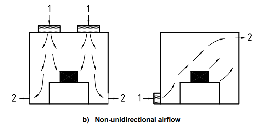
The cleanroom airflow pattern and HVAC design will determine which air change rate calculation is appropriate. Turbulence, eddies, processes equipment, and pressure differentials all influence air exchange rates as exiting and returning air interact throughout the cleanroom. One must first consider whether the airflow design is unidirectional or non-unidirectional.
ISO standards outline unique air change calculation methods for unidirectional vs non-unidirectional cleanrooms.
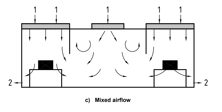
- In non-unidirectional and mixed flow cleanrooms, use the air changes per hour (ACH) calculation method.
- In unidirectional airflow cleanrooms, calculate air change with average airflow velocity.
Calculating Air Change Rate (ACR) in Non-Unidirectional Cleanrooms (ISO 6 – ISO 8)
The chart below is found within ISO 14644-4:2004 Design, Construction, & Start Up.
The calculation below is based on a ceiling height of 3 meters.
| Ceiling Height = 3.0 Meters | Low-End ACH (m3/m2 x h) | High-End ACH (m3/m2 x h) |
| ISO 6 | 70 | 160 |
| ISO 7 | 30 | 70 |
| ISO 8 | 10 | 20 |
What is the Formula for Cleanroom Air Changes Per Hour (ACH)?
Calculate ACR with ACH when cleanroom airflow is non-unidirectional or mixed airflow.
The formula for calculating cleanroom ACH:
Air changes / hr = CFM X 60min / Volume of Room
The rate of cubic feet per minute is recalculated into cubic feet per hour, which is then divided by the volume of the room (height X width X length).
Below we’ll outline the basic principles of air change rates, but also provide a more rational outline of standardized air change tables for specific cleanrooms. Most importantly, we’ll help you understand the proper air change calculation rate based on the industrial standards of your facility’s cleanroom.
- Most non-unidirectional or mixed airflow cleanrooms fall within ISO 5 – ISO 8 cleanrooms
- ACH calculations must adjust the calculation for ceiling height
- Applications: Pharmaceutical, health, biosciences, packaging, isolation, handling
Don’t Use Air Velocity to Calculate Air Exchange in a Non-Unidirectional Cleanroom?
If the airflow in a cleanroom is non-uniform (non-unidirectional airflow) air velocity readings will not provide an accurate sample of inferential data points. Turbulence, eddies, processes equipment, and pressure differentials all influence velocity readings as exiting and returning air interact throughout the cleanroom. Data points would not represent a normal distribution of the actual room conditions. Non-unidirectional air patterns measured with average velocity readings often produce confusing, misleading, or extraneous data.
Calculating Cleanroom Air Change Rates for ISO 1 – 5
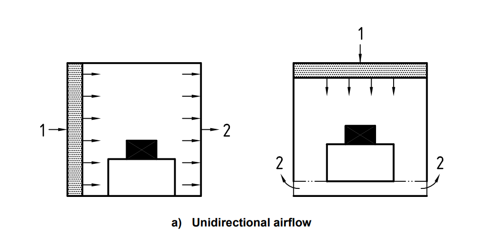
In cleanrooms with unidirectional airflow, air exchange rate is calculated by air velocity sampling.
It’s suggested that in cleanrooms with unidirectional airflow patterns (ISO CLASS 1 – 5), air exchange rates can be calculated by average air velocity. In some cases, ISO Class 6 cleanrooms may also require unidirectional air.
What is Unidirectional Air Flow?
Unidirectional airflow patterns carry horizontally or vertically across space in parallel movement, usually between 60 – 90 FPM. Airflow remains within 18 degrees of parallel with sufficient velocity to sweep away particles before affixing to surfaces.
Unidirectional ACR Charts (Average Air Velocity)
| Velocity Threshold | ISO 5 | ISO 4 | ISO 3 | ISO 2 |
| Low-End Velocity (Meters/Second) | 0.2 | 0.3 | 0.3 | 0.3 |
| High-End Velocity (Meters/Second) | 0.5 | 0.5 | 0.5 | 0.5 |
Cleanroom Applications for Average Air Velocity
- Benchmark for ISO 2 – ISO 5 facilities
- Cleanroom airflow is unidirectional
- Airflow velocity is independent of the ceiling height
- Electronics and microfab facilities
- Uniform velocity throughout the entire space
- Air flows through the entire cross-section of a clean zone
- Steady velocity and approximately parallel streamlines of 60 – 90 FPM
- Directional airflow can be attained both vertically and horizontally.
Fan Filter Coverage for Unidirectional Cleanrooms
In most cases, a unidirectional airflow cleanroom requires ISO 5 or better air and nearly 100% fan filter ceiling coverage; fan filter coverage is not a particularly revealing metric. Fan filter coverage is commonly referenced in IEST, FED, and ASHRAE standards, however not referenced in latest ISO documentation for cleanroom design.
As noted previously, air changes per hour in unidirectional cleanrooms is calculated by air velocity readings. This is outlined in IES Standard RP CC 002-86 “Laminar Flow Clean Air Devices”, which calculates the appropriate air velocity of a unidirectional cleanroom at 90 FPM.
All unidirectional cleanroom measurements will fall (generally) within a 20% benchmark range of 90 FPM. A fixed fan filter rate of 90 FPM allows a cleanroom designer to simply install additional fan filter units as needed until arriving at the desired classification. The number of units required may vary throughout different bays of the facility. A facility could have up to 100 partitioned bays, with one process happening in each bay.
Fan Filter Coverage for Non-Unidirectional Cleanrooms
Fan filter coverage is a common cleanroom benchmark outlined in Fed. Standard 209E (now outdated) and other case models.
The most common question about cleanroom construction — “How much is this going to cost?”. Establishing the baseline cost of each fan filter *multiplied by* the number fan filter units per sq. foot simplifies cleanroom cost calculation. One could regard fan filter coverage calculation for cleanrooms as a quick reference tool in the early design stages.
Without knowing the ballpark quantity of fan filter units required for a cleanroom, estimating the cleanroom’s initial cost is challenging. The performance and cost of a fan filter unit vary, hence fan filter coverage estimates are helpful for cleanroom specialists after establishing other criteria.
Fan filter coverage charts help simplify the dialogue between preliminary engineers and end-users (buyers) and make quotes more transparent. The final performance still requires the input of many other variables.
Summary: Fan filter coverage calculation is not referenced by ISO cleanroom design standards. It’s a valuable tool for specialists to quickly estimate build costs. Fan filter coverage provides a simple way to calculate cleanroom construction costs during preliminary engineering, but it is considered a secondary factor to the final efficiency and performance of the cleanroom.
How Do We Calculate Fan Filter Coverage?
No. of FFUs = (Air Changes/Hour ÷60) x (Cubic ft. in room÷ FFU CFM*)
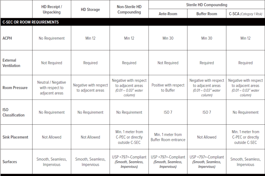
Cleanroom Air Change Rates and Tables for USP Standards
USP 797 and USP 800 cleanrooms for sterile and hazardous drug processes also have unique air change requirements. A flow hood within the primary control area does, in fact, influence the overall air change rate of the room as a whole. Sterile or hazardous compounding has a much different airflow requirement than a microelectronics cleanroom.
Cleanroom Air Exchange Calculation Variables
These models are most common because they are easily referenced during preliminary engineering. The final calculation requires more thorough means to achieve ISO recovery rates, and ensure that airborne particulate levels rarely exceed class limits. For example, a decay equation measures particulate between the first and second test sampling. This helps cleanroom designers understand particulate levels after a doorway or pass-throughs opens and closes. Further variables, such as dispersion rates from personnel and machinery, additional clean air devices, surface deposition, and air handling design also influence the final particle contributions.
Why Do Cleanroom Air Change Rates Vary Despite ISO Cleanroom Standards?
Cleanroom ACH requirements are largely determined by contamination levels. A cleanroom built at the low end of air change benchmarks may be adequate when the cleanroom requires few operators during relatively clean processes.
Facilities account for particulate expectations by extending air change rates, or sometimes with built-in, variable airflow systems. Some cleanroom facilities opt for demand-controlled filtration systems which optimize air recirculation based on real-time particle counts. Likewise, variable drive fan filter provides parameters for preset adjustment in the case that a cleanroom is vacant for extended periods. Because cleanrooms generally remain powered 24/7, throttling back fan drives reduce overall energy cost.
Why is Cleanroom Air Change Based on a Range?
In nearly every example, the air change rate is established by a low and high range for a simple reason…it’s not an exact science.
The high end (48 ACH) of an air exchange rate in an ISO 8 cleanroom is nearly 9 times cleaner than the low end (5 ACH) of 146144-4 standards. This doesn’t provide a lot of clarity for contractors or project leads when budget, product safety, or operating cost is of paramount importance.
Air change tables suggest a high and low range because these tables do not account for complexities of achieving a final cleanliness level in a specific cleanroom. Further, some facilities may over-spec their air system for more favorable temperature and humidity control. However, in most cases, facilities build toward the lower end of the threshold to maximize air efficiency. Nonetheless, air change tables allow a gross estimate of the size and quantity of fan filter units, which is a significant factor in the overall cost per square foot.
A Reliable Test Result Requires a Reliable Test Method.
It must be known that not every calculation method is appropriate for every facility. Depending on the design of the cleanroom and HVAC components at hand, the above calculation methods require clarity and justification.
Benchmarks establish guidelines and best practices, however, the ACR of a cleanroom in motion is more variable than one would think. Project leads and contractors often lack data for comparison of build variation within high-tech or niche manufacturing facilities. Factors include the use of air handlers vs modular fan filter systems, the efficiency of filters and motors, variable air change rates per area, and overall pressure resistance.
“There is no agreement on a recommended ACR rate. Most sources suggest a range of rates, while these ranges tend to be wide and do not provide clear guidance to designers who need to select a set ACR value to specify equipment sizes.”
US Dept. of Energy Study
Why Might a Facility Avoid Generic Tables for ACR Benchmarks?
An aggressively designed airflow rate requires a more powerful HVAC system, more fan filter coverage, and extends overhead operating costs. Sometimes a process rapidly evolves toward smaller and more sensitive components, or a facility expects increased output and sensitivity in the near future. An oversized air handling system easy mediates air demand when production scales, requires a cleaner classification or involves expanding the number of cleanroom suites.
Air Change Rates 2.0
A cleanroom design incorporates the analysis and deliberation at every intersection between manufacturers, architects, engineers, HVAC specialists, and facility operations staff. Air change tables often provide points of inference and consideration but have no traceable technical basis for contamination control. Initial estimates of air exchange rates must reflect final conditions and adjust for less obvious parameters such as the offset of heat gains, air leakage, and recovery rate,
Air change tables are important tools during initial discussions, however, efficiency and cleanliness have far more elusive parameters than square footage, average airflow velocity, or hourly air change rates. Experienced cleanroom designers understand that other factors such as proper fan size selection, area coverage, and room design have nefarious consequences if not considered early. A cleanroom system requires many co-dependent evaluations and preliminary decisions for a strong foundation.
Conclusions
- In non-unidirectional and mixed flow cleanrooms, use the air changes per hour (ACH) calculation method.
- In unidirectional airflow cleanrooms, calculate air change with average airflow velocity.
The fundamental goal of each cleanroom is unique to its process, and so is the science behind its design. For most facilities, speaking with a controlled environment specialist is the fastest path from clean idea to a clean build.
The information herein should help you do two things: clarify and justify an air exchange rate calculation method, and understand which is most applicable for your cleanroom. However, it does not constitute a recommendation for your cleanroom.